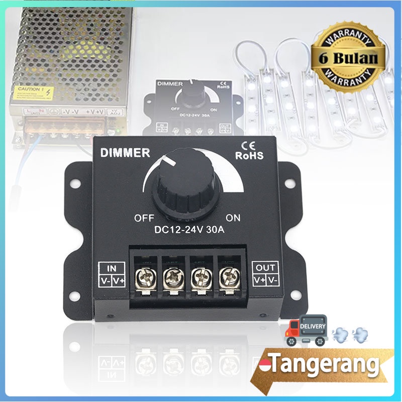
Jual LED Dimmer DC 12V 24V 30A Single Colour Pengatur Kecerahan Led Circuit Diagram This automatic light dimmer circuit makes it possible to control a lighting system so that it turns on or off slowly. The circuit works this way: when switch S1 is closed, the capacitor C1 is slowly charged. Once the voltage at C1 reaches 0.6, transistor T1 begins to conduct and the LED also begins to light.
In this LED Dimmer Circuit, 555 timer works as an astable multivibrator and generates PWM pulses. The circuit includes the timing components like Resistors, potentiometer, and capacitor Thus, the potentiometer is there to adjust the duty cycle of the PWM signal. The higher the duty cycle, the greater will be the light intensity, the light However, the dimming effect can be perhaps implemented by connecting the series LED section of the LED bulb with the IC 555 circuit, as indicated in the following diagram: We know that an LED bulb circuit is nothing but a small AC to DC SMPS circuit, which employs a small ferrite transformer for stepping down the mains voltage to a lower LED DC

Automatic Light Dimmer Circuit Diagram
Automatic Light Dimmer Circuit Diagram. The light then comes on. When the light switch is turned off, C2 is discharged via P1, R2 and D6. When the potential across C2 drops, the brightness of the LED diminishes, so that the p.d. across R3 also drops. The increasing resistance of R3 effects phase angle control of the triac so that the light is

The automatic Daylight dimmer circuit. But in Figure 2 will work to reverse the first. Also, choose the switch-S2 to LDR1 way, then this circuit becomes the automatic daylight dimmer switch circuit. This can control lamps in the Warehouse, if open the door and have sunlight to LDR, it will cause the lamp to glow. LDR1 in Figure 2 is a PTC type.
LED Dimmer Circuit with 555 Timer Circuit Diagram
Hii Friends, Today i am show you how to make a automatic light dimmer circuit at home. So let's start it. All Component details show in the video. So watch v
